
 Reading time: 2 minutes
Quick and easy configuration to make two Cisco Nexus 9000 Series devices to appear as a single device to downstream switches. Here’s the configuration to create a virtual port channel (vPC). Don’t forget to enable the necessary feature sets (feature vpc etc)
PEER KEEPALIVE CONFIGURATION NEXUS-1
feature vpc
feature interface-vlan
vpc domain 1
Now run this command to view the role show vpc role
vlan 12
  name keepalive
  vrf context keepalive
interface Vlan12
  vrf member keepalive
  ip address 10.254.1.1/24
  no shut
interface Ethernet1/3
  switchport
  switchport access vlan 12
  no shut
Peer-Keepalive configuration on Nexus-1:
vpc domain 1
peer-keepalive destination 10.254.1.2 source 10.254.1.1 vrf keepalive
PEER KEEPALIVE CONFIGURATION NEXUS-2:
feature vpc
feature interface-vlan
vpc domain 1
Now run this command to view the role show vpc role
vlan 12
  name keepalive
  vrf context keepalive`

interface Vlan12
  vrf member keepalive
  ip address 10.254.1.2/24
  No shut

interface Ethernet1/3
  switchport
  switchport access vlan 12
  No shut
Peer-Keepalive configuration on Nexus-2:
vpc domain 1
peer-keepalive destination 10.254.1.1 source 10.254.1.2 vrf keepalive
Peer-Keepalive verification
show vpc peer-keepalive`
CONFIGURE THE VPC PEER-LINK (same on Nexus-1 and Nexus-2)
feature lacp
interface ethernet 1/4-6
  description *** VPC PEER LINKS ***
  switchport
  channel-group 12 mode active
vlan 10
  no shut
interface port-channel 12
  description *** VPC PEER LINKS ***
  switchport
  switchport mode trunk
  switchport trunk allowed vlan 10
  vpc peer-link
  spanning-tree port type network
  no shut
CONFIGURE VPCS TO DOWNSTREAM DEVICES
interface Ethernet1/1
  description Connected to Nexus-3
  switchport
  no shut
  channel-group 10 mode active

interface port-channel10
  description Connected to Nexus-3
  switchport mode trunk
  vpc 10
  no shut

interface Ethernet1/2
  description Connected to Nexus-4
  switchport
  channel-group 11 mode active
  no shut

interface port-channel11
  description Connected to Nexus-4
  switchport mode trunk
  vpc 11
  no shut
CONFIGURE VPCs ON NEXUS-3 TO UPSTREAM DEVICES
feature lacp
interface Ethernet1/1
  description Connected to Nexus-1
  switchport
  no shut
  channel-group 11 mode active

interface Ethernet1/2
  description Connected to Nexus-2
  switchport
  channel-group 11 mode active
  no shut

interface port-channel11
  description Connected to Nexus-1&2
  switchport mode trunk
  no shut
CONFIGURE VPCs ON NEXUS-4 TO UPSTREAM DEVICES
feature lacp
interface Ethernet1/1
  description Connected to Nexus-1
  switchport
  no shut
  channel-group 11 mode active

interface Ethernet1/2
  description Connected to Nexus-2
  switchport
  channel-group 11 mode active
  no shut

interface port-channel11
  description Connected to Nexus-1&2
  switchport mode trunk
  no shut
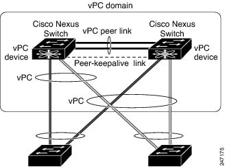
What we want is to have Nexus-1 and Nexus-2 appear as one device to downstream devices as shown here: